
So, I decided to build a Pi based ZX Spectrum emulator, inside a ZX Spectrum case. Celebrating 40 years of the Spectrum and all that…
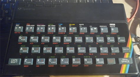
Before going any further, which version of the Spectrum is it?
Well, looking at the keyboard colour, it looks like an Issue 1. Pity it didn’t have a PCB inside it. It might have been repairable and worth something.
But the serial number is 001-410698, making it an Issue 2.

I’ll have to look into this more.
Anyway…
Why am I bothering to do this?
Well, I like Spectrum games. Currently I use Raspbian and FUSE on a Raspberry Pi 4 to fulfill my Sinclair needs, using this keyboard:
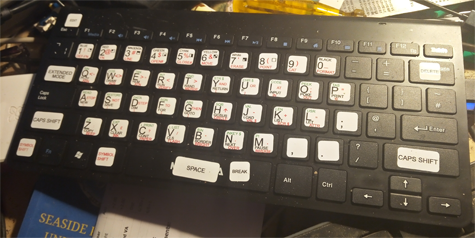
Clearly, while this works, it is less than ideal. My first thought was to try to connect a Spectrum keyboard to the Pi4, but after seeing the mass of wiring involved, and how untidy it would look, I decided to just build another system.
Also I’m writing a wrong. Back in about ’92 I fitted a Spectrum and ZX81 into two old terminal keyboards I bought at auction, thus ruining them.
I actually mounted the ZX81, along with an old portable B/W TV into the case of and old ADM-3 terminal.

The last time I saw it, it was in the teaching lab I used to work in, in room K110 of Staffordshire University’s School of Computing’s Octagon Building, connected to an I/O interface kit. Note: it was better than the awful 6502 based hex-programmed systems that were being used for teaching at the time.
These days, you’d just use an Arduino, but 1992 is like Echo Beach… far away in time!
Anyway, I set myself rules:
- The outside of the case should be as intact and unmolested as possible.
- The Power and Video Out ports would be in the same locations as on the original.
- The USB ports would sit in the expansion slot.
So, as it looks:

This would leave the EAR and MIC holes free for the mounting of control buttons.
So… On we go…
Parts required
- Pi Zero (with the GPIO headers populated) of some sort – I used a Pi Zero W v1.3
- A MicroUSB PSU (preferable an official Pi one),
- MicroSD card to install the system on
- A ZX Spectrum case, hopefully with a working keyboard membrane inside
- 2 small bits of Veroboard
- 5way and 8way keyboard Molex connectors
- 5way and 8way angled GPIO angled header pins
- 8x1N4148 diodes
- 13 GPIO jumper leads, female ended
- USB OTG pigtail (Amazon)
- 2x MicroUSB extension leads (Amazon)
- MiniHDMI plug to MicroHDMI socket pigtail (Amazon)
- a slim 4 port USB hub (Amazon)
Tools and Sundries
- Screwdriver for the case screws on the Spectrum
- Soldering kit
- Small files for case “adjustment”
- Glue Gun
- Milliput epoxy putty
- Duct/Gaffer/Bodge tape (I use Gorilla Tape)
Case Modifications
Carefully open the Spectrum case, and unplug the keyboard ribbons. Then remove the main board. It won’t be needed again. Resell it if you want.
And, disregarding Rule 1 (above) I immediately started hacking away at the case.
To mount the USB hub, the rear middle case fixings needed to be removed, and the Expansion hole needed to be made about 3mm deeper and 6mm wider. The Power hole had to be stretched too, as did the Video out one.
So, out with the files and Milliput!
Fitting it all in
The wiring is a mess. the cables are too long, and some are a bit too “sturdy” to bend properly. So I have to fit the mess on the left, into the case on the right. Without fouling the case fixings.

Tight, but only just!

I *could* have made my own cables to fit, but this is just a prototype build to get it working. Maybe next time, if I build another one (a Spectrum+ maybe, using a Pi3 or Pi4).
I was not yet adding the hardware for the Spectrum keyboard to be connected, as I was having trouble with the circuit and it detecting spurious signals. That will be for next time.